In Part 1, I provided some clarity to the definitions for pressure terminology. In the second part of this series, I’ll discuss how these pressure terms apply to selecting the right fan for an application.
Fan Selection Pressure
The selection of the right fan for an application is based on flow and pressure. First, we determine how much air flow is needed in the ventilation system to perform its desired function. Then we determine the amount of pressure that the fan needs to overcome in order to provide the required air flow. The pressure that is most commonly used in the selection process is total static pressure. As we learned last week, it is the sum of all the static pressure drops across all elements in the ventilation system.
To illustrate the use of total static pressure in the selection process, we will create an example ventilation system. The system’s desired function is to provide comfort cooling for a small manufacturing facility. The required air flow to keep the inside temperature the same as the outside is 10,000 CFM. The customer also wants filtered supply air, so in addition to a panel fan, the static pressure elements of the system are a filter and a backdraft damper on the supply side and a louver on the exhaust side. If this were a real design situation, we would use the manufacturer’s information to determine the static pressure drops of each of these elements at our 10,000 CFM air flow rate. However, for this example we will just assume that the static pressure drops are 0.35” w.c. for the filter, 0.05” w.c. for the backdraft damper, and 0.10” w.c. for the louver. Therefore, the total static pressure that we will use for the fan selection is 0.50” w.c.
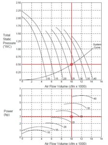
To the right is an example of the selection curves for a 24” panel fan. On the top graph, the vertical axis is Total Static Pressure in inches of water column and on the horizontal axis is Air Flow in cubic feet per minute. The numbers to the right of the curves tell us the blade pitch angle. On the bottom graph, the vertical axis is Power in horsepower and on the horizontal axis is Air Flow in cubic feet per minute.
On the top graph, the fan selection point is at the intersection of 0.50” w.c. for Total Static Pressure and 10,000 CFM for Air Flow Velocity. That will tell us the blade pitch angle required for the fan blades. On the bottom graph, if we go to the point where the same blade pitch angle intersects the 10,000 CFM line then draw a straight line to the left, that will tell us the horsepower of the motor required to provide the 10,000 CFM of air flow.
Now maybe you are wondering about velocity pressure and how it factors into the fan selection process. After all, the Total Pressure that the fan has to overcome to provide the 10,000 CFM includes the velocity pressure. In the US, most fan manufacturers will use Total static Pressure in their pressure and flow selection graph. However, in selecting the motor horsepower, they will have added the velocity pressure to ensure that the motor has enough power. In our example, the velocity pressure is 0.63” w.c. The 3 horsepower motor that is selected for this application has enough power to overcome 1.13” w.c. of Total Pressure in our example ventilation system to provide 10,000 CFM.
I hope that this two part series on Understanding Pressure Terminology has clarified your understanding of the terms used to describe and measure pressure. A better understanding of the terminology will lead to better designs for ventilation systems and selecting the right fan for the application.
