One of the ventilation system design principles for an industrial facility is to determine the amount of air flow needed to remove internal heat load. When the solar heat load is the only heat load, the activities inside or the purpose of the facility will determine what is an appropriate air change rate. But what happens if there is a heat source internal to the building? In this article, I will discuss some of the ventilation system design principles that we use to remove internal heat loads.
Internal Heat Sources
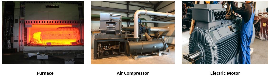
Heat sources that may be internal to a facility include ovens, furnaces, turbines, compressors, electric motors and reciprocating engines. Determining the amount of heat that these internal sources give off is necessary to determine how much additional airflow is required. Most manufacturers will provide data on the heat rejection from their equipment. Another way to determine the amount of heat generated from these sources is to determine how much power they consume. For example, knowing the operating hours and monthly natural gas consumption may be the easiest way to determine the amount of heat generated by an oven or furnace.
Temperature Change
The obvious impact that an internal heat source has on a facility is that it will increase the inside temperature. But determining how much of a temperature increase is tolerable depends on a number of factors including maximum operating temperatures for equipment and the number of people working around the equipment. When minimizing the heat exposure to people is the determining factor, the tolerable temperature increase should be as close to zero as practical to minimize the heat impact on worker productivity.
Additional Air Flow Required
The air flow required to remove the heat from an internal source must be added to the air flow required to remove the solar heat load. To determine the additional air flow required, the following formula should be used where BTU/Hr equals the total heat generated from all internal sources and delta T (∆T) equals the tolerable temperature increase above ambient temperature inside the facility:
Additional CFM = (BTU/Hr) ÷ (1.085 x ∆T)
As an example, assume the total internal heat sources equal 500,000 BTU/Hr and the tolerable temperature increase is 5 degrees F:
Additional CFM = 500,000 ÷ (1.085 x 5) = 92,166 CFM
Therefore, when designing the ventilation system for our example facility, 92,166 CFM is the amount of air flow needed. If the fans are properly selected for our example facility to handle the combined internal heat loads, the inside temperature for our example facility will never be more the 5 degrees F higher than the outside temperature regardless of how hot it gets outside.
Combustion Air
If the air intake for an oven, furnace, turbine or reciprocating engine is inside the facility, the amount of combustion air required by the equipment will need to be reduced from the required exhaust air flow. If not, the pressure balance in the space will be less than expected.
Fan Location
Fan location is also an important factor to consider when there is an internal heat source. Ideally, the ventilation system exhaust should be located on the roof directly above heat source. This will minimize the impact of the heat source on people working around it. If locating the exhaust on the roof is not possible, then it should be located as high up on the closest building wall as possible keeping in mind that the supply and exhaust locations should be on opposite walls.
Conclusion
Heat sources inside a facility add challenges to the design of a general ventilation system. We have helped many customers overcome this challenge with a ventilation system design that we guaranty will take care of the heat load. If you are building a new building or need to add a ventilation system to an existing building that has an internal heat source, let Eldridge help you create a success environment inside your facility.