Redesigning ventilation systems often requires problem solving with Fan Laws. The three Fan Laws use the relationship between fan air flow rate, static pressure, speed and horsepower to determine the outcome when one of the variables has changed. In this article, I’ll explain each of the fan laws, their limitations and how we can do some problem solving with Fan Laws.
Fan Laws
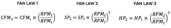
Here are the three fan laws:
The limitation to using the fan laws is that they only can be applied when physical characteristics of the fan are unchanged. If we change the configuration of the fan , then the fan laws can’t be applied to the new curve. That means the propeller characteristics such as diameter, number of blades, blade pitch angle, and hub size, or and the geometry of the fan inlet or outlet must remain the same.
Here are brief explanations of each law:
Fan Law 1: tells us that the change in air flow rate of a fan is proportional to the change in speed of the propeller. If the propeller speed is increased by 10%, the air flow rate will also increase by 10%.
Fan Law 2: tells us that the change in total static pressure of the ventilation system will increase by the square of the change in propeller speed of the fan. If the propeller speed is increased by 10%, the total static pressure will increase 21%.
Fan Law 3: tells us that the change in horsepower required by the fan to turn the propeller will increase by the cube of the change in propeller speed of the fan. If the propeller speed is increased by 10%, the horsepower required to turn the propeller will increase 33.1%.
Problem Solving
We were recently asked to help a customer with a noisy direct drive fan. The customer had installed a wall mounted exhaust fan in an area that previously had no ventilation equipment. Unfortunately, the sound level from the fan was considered to be too noisy by the workers closest to it. Rather than remove the fan and have no ventilation, we recommended that the customer use a VFD to turn the fan down to an acceptable sound level. The customer agreed and using a VFD, the acceptable noise level was found to be at a fan speed of 1325 RPMs.
At the reduced speed, the customer wanted to know what was the reduced air flow from the fan. It was initially providing 30,000 CFM at .125 inches of static pressure with a 5 HP motor turning at 1750 RPMs. To determine the reduced air flow rate, we used Fan Law 1 and solved for CFM2:
5CFM2 = CFM1 x (RPM2 /RPM1)
1CFM2 = 30,000 x 1325/1750
6CFM2 = 22,714
Fan Law 2 told us that the impact of reduced air flow would result in a decrease in static pressure:
2SP2 = SP1 x (RPM2/RPM1)2
1SP2 = .125 x (1325/1750)2
3SP2 = .072
Using Fan Law 3 we can determine the reduced horsepower requirement for the fan:
0HP2 = HP1 x (RPM2/RPM1)3
1HP2 = 5 x (1325/1750)3
4HP2 = 2.17
Conclusion
Using the Fan Laws, we told the customer that the fan would provide 22,714 CFM operating at 1325 RPM. We also pointed out that the lower air flow reduced the air change rate. Therefore, they can expect a higher inside temperature because the solar heat load will not be completely dissipated.
Solving ventilation problems is what we do at Eldridge and the Fan Laws are just one of the tools that we use. If you have a ventilation problem, call a ventilation expert at Eldridge. Using our skills and knowledge gained with 76 years of experience to design a solution to fit the problem.