
Industrial ventilation systems are designed to move a specific volume of air while maintaining the pressure and performance requirements of a facility. When an existing ventilation system needs more airflow, engineers may be able to improve performance by adjusting fan speed rather than replacing the entire fan or redesigning the ductwork. Understanding the three basic fan laws is essential to determining how these adjustments affect airflow, static pressure, and horsepower requirements.
At Eldridge, the three basic fan laws are important tools when evaluating industrial ventilation system redesigns. These laws describe the relationship between fan speed, airflow, pressure, and horsepower. They allow engineers to predict how a fan’s performance will change when its rotational speed increases or decreases, provided the appropriate operating conditions remain consistent.
The fan laws are especially useful when evaluating industrial ventilation systems and applications where increasing airflow without replacing existing equipment is a priority.
In this article, we explain the three basic fan laws, provide the mathematical formulas used to calculate fan performance, discuss their limitations, and demonstrate how they can be applied to an industrial ventilation system redesign.
What are the 3 Basic Fan Laws?
The three basic fan laws, also known as fan affinity laws, describe how changes in fan speed affect three important performance characteristics:
- Fan Law 1: Airflow (CFM) – Airflow changes in direct proportion to fan speed.
- Fan Law 2: Static Pressure – Static pressure changes in proportion to the square of fan speed.
- Fan Law 3: Horsepower – Horsepower requirements change in proportion to the cube of fan speed.
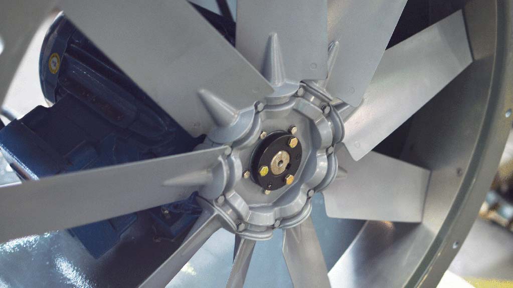
Before applying these formulas, it is important to understand their limitations. The simplified fan laws assume that the fan configuration remains unchanged, including the propeller diameter, number of blades, blade pitch angle, and hub size. They also assume comparable inlet and outlet geometry, air density, and operating conditions.
The formulas below are used to estimate changes in fan performance when rotational speed changes while the fan diameter remains constant.
Fan Law 1: Airflow and Fan Speed
The first fan law states that the airflow produced by a fan is directly proportional to its rotational speed.
In other words, increasing the fan’s revolutions per minute (RPM) by a certain percentage will increase its theoretical airflow by the same percentage.
Fan Law 1 Formula:
CFM₂ = CFM₁ × (RPM₂ / RPM₁)
Where:
- CFM₁ = Original airflow rate (cubic feet per minute)
- CFM₂ = New airflow rate (cubic feet per minute)
- RPM₁ = Original fan speed
- RPM₂ = New fan speed
For example, if a fan operates at 1,000 RPM and produces 15,000 CFM, increasing its speed to 1,100 RPM would theoretically increase airflow to 16,500 CFM.
This relationship is useful when determining how much additional airflow an existing industrial exhaust fan can provide without changing its physical size.
Fan Law 2: Static Pressure and Fan Speed
The second fan law states that the static pressure produced by a fan changes proportionally to the square of its rotational speed.
This means that pressure increases faster than airflow as fan speed increases.
Fan Law 2 Formula:
SP₂ = SP₁ × (RPM₂ / RPM₁)²
Where:
- SP₁ = Original static pressure
- SP₂ = New static pressure
- RPM₁ = Original fan speed
- RPM₂ = New fan speed
For example, increasing fan speed by 10% does not increase static pressure by only 10%. Instead, the pressure increases by approximately 21%.
This relationship is particularly important in industrial ventilation systems because increasing airflow can also affect building pressure, ductwork performance, and the amount of resistance within the ventilation system.
When evaluating a ventilation redesign, engineers must consider whether the existing system can accommodate the additional pressure without creating unwanted operating conditions.
Fan Law 3: Horsepower and Fan Speed
The third fan law states that the horsepower required to operate a fan changes proportionally to the cube of its rotational speed.
Of the three fan laws, this relationship is particularly important when evaluating motor capacity and determining whether an existing fan can safely operate at a higher speed.
Fan Law 3 Formula:
HP₂ = HP₁ × (RPM₂ / RPM₁)³
Where:
- HP₁ = Original horsepower requirement
- HP₂ = New horsepower requirement
- RPM₁ = Original fan speed
- RPM₂ = New fan speed
For example, increasing fan speed by 10% increases the theoretical horsepower requirement by approximately 33.1%.
Increasing fan speed requires careful consideration of the motor’s horsepower rating, fan shaft power, drive system limitations, and operating conditions.
Even if an existing motor appears to have additional capacity, engineers should verify that the motor, belts, sheaves, bearings, and fan assembly can accommodate the increased operating speed and power requirements.
What Applications Use the 3 Basic Fan Laws?
The three basic fan laws are frequently used when evaluating industrial ventilation system redesigns, particularly when a facility needs additional airflow but wants to avoid replacing existing fans.
In many industrial applications, changing the fan’s rotational speed can provide an alternative to installing larger equipment or making extensive ductwork modifications.
However, increasing fan speed also increases static pressure and horsepower requirements. Applying all three fan laws allows engineers to evaluate these relationships before making changes to an existing ventilation system.
Consider an industrial ventilation redesign application that Eldridge has encountered:
- The customer wanted to increase airflow from their existing belt-driven exhaust fans.
- Each exhaust fan was moving 15,000 CFM of air at a rotational speed of 1,000 RPM.
- The exhaust fan motors were rated at 1,750 RPM and 5 HP, but the fans were using a peak horsepower of 3.75 HP.
- Air was supplied to the building through louvers with a static pressure of 0.15 inches of water gauge (in. w.g.).
- The customer did not want to increase the building’s negative static pressure.
- The customer wanted to determine how much additional airflow each fan could provide without exceeding the assumed 5 HP power limit by changing only the sheave sizes.
To evaluate the proposed redesign, we applied the three basic fan laws.
Step 1: Apply Fan Law 3 to Determine the New RPM
We started with Fan Law 3 to determine the maximum theoretical fan speed based on the available horsepower.
The formula is:
RPM₂ = (HP₂ / HP₁)^(1/3) × RPM₁
Substituting the known values:
RPM₂ = (5.0 / 3.75)^(1/3) × 1,000
RPM₂ = 1.1006 × 1,000
RPM₂ = 1,101 RPM
Based on the horsepower calculation, the fan could theoretically increase its operating speed from 1,000 RPM to approximately 1,101 RPM.
Step 2: Apply Fan Law 1 to Determine the New Airflow
Next, we applied Fan Law 1 to calculate the new airflow rate from each exhaust fan.
The formula is:
CFM₂ = CFM₁ × (RPM₂ / RPM₁)
Substituting the known values:
CFM₂ = 15,000 × (1,101 / 1,000)
CFM₂ = 15,000 × 1.101
CFM₂ = 16,515 CFM
By increasing the fan speed to approximately 1,101 RPM, each exhaust fan could theoretically increase airflow from 15,000 CFM to 16,515 CFM.
This represents an increase of 1,515 CFM per fan.
Step 3: Apply Fan Law 2 to Determine the New Static Pressure
Finally, we applied Fan Law 2 to determine how the increased airflow and fan speed would affect static pressure.
The formula is:
SP₂ = SP₁ × (RPM₂ / RPM₁)²
Substituting the known values:
SP₂ = 0.15 × (1,101 / 1,000)²
SP₂ = 0.15 × 1.2122
SP₂ = 0.18 in. w.g.
The calculation indicates that the pressure would increase from 0.15 in. w.g. to approximately 0.18 in. w.g.
This increase was important because the customer specifically wanted to avoid increasing negative static pressure within the building.
The pressure calculation provided an estimate of the impact of the proposed speed adjustment. Actual building pressure and fan operating conditions would need to be verified through system evaluation and field measurements.
Conclusion
By correctly applying the three basic fan laws, we were able to provide the customer with a theoretical maximum airflow estimate of 16,515 CFM per exhaust fan by changing only the sheave sizes.
However, the increased airflow also meant that the customer would need to increase the available supply air through the building’s louvers to help maintain the desired building pressure.
Although the customer ultimately decided to pursue a different approach, understanding and applying the three basic fan laws provided valuable information to help determine the available options and associated costs of redesigning the ventilation system.
The fan laws are valuable engineering tools for evaluating industrial ventilation performance, but calculations should always be considered alongside actual fan curves, motor limitations, system resistance, air density, and operating conditions. The theoretical results must be verified before implementing changes to an existing system.
Whether your industrial ventilation system needs a simple adjustment to existing sheaves or a more extensive redesign involving additional fans, Eldridge can help evaluate your requirements and identify solutions that align with your facility’s performance goals and budget.
Contact Eldridge to discuss your industrial ventilation system redesign and explore the right fan and airflow solutions for your application.